Assembly Programming on Atmega328p
Lecture 1
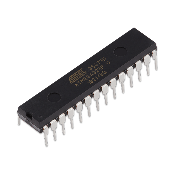
The Atmega328p microcontroller is a small computer on a single integrated circuit which contains a processor core, memory and programmable input and output peripherals.
Why assembly?
-
Code is optimized for speed & space;
-
Assembly coding enables you to learn H/W organization of microcontroller;
-
Assembly code can take full advantages of controller H/W features;
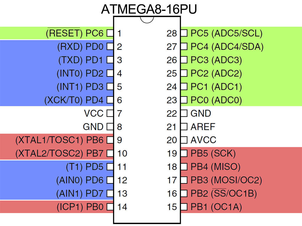
Hardware Organization
Instruction Set
Arithmetic and Logic |
ADD |
SUB |
AND |
OR |
MUL |
Branch |
JMP |
RCALL |
RET |
CPI |
BREQ |
Data transfer |
MOV |
In |
OUT |
LDI |
STS |
Bit-by-bit test |
ROL |
CBI |
CLC |
SWAP |
ROR |
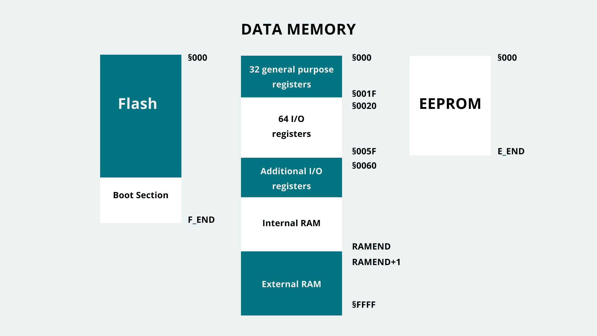
Memory Map
Blink led
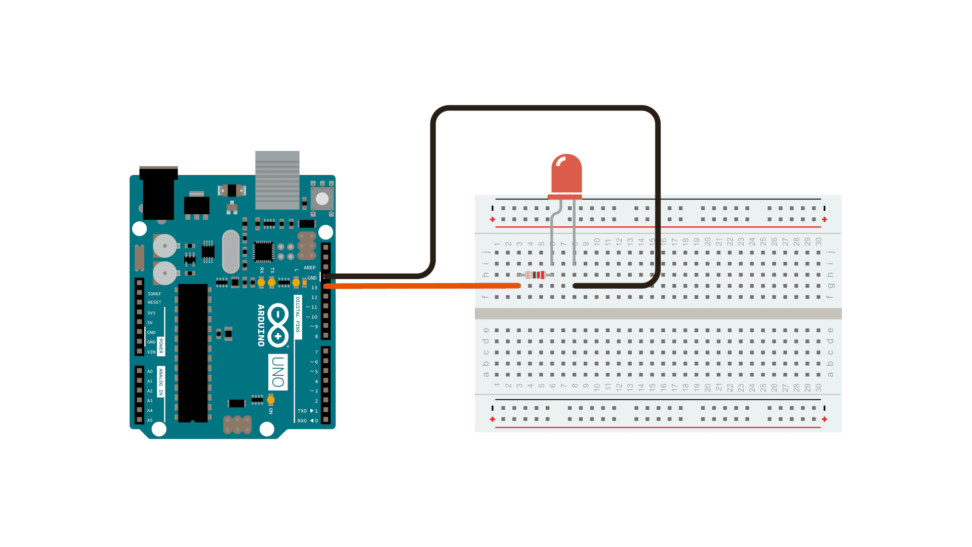
The purpose of this section is to provide the fundamentals for building an example to turn an LED on and off. This objective will be achieved through the analysis of the programs led.ino and led.S built using functions from the AVR Instruction Set Manual.
Item |
Quantidade |
Plataforma Arduino |
1 |
Cabo USB |
1 |
Protoboard |
1 |
Led |
1 |
Resistor de 200 ohms |
1 |
Code
We need to create two files. The first file in c++ (extension .ino) and the second file in assembly (extension .S). Both with the same name and in the same directory.
//-------------------------
// C Code for Blinking LED
//-------------------------
extern "C"{
  void start();
  void led(byte);
}

void setup(){
  start();
}

void loop(){
  led(1); delay(200);
  led(0); delay(200);
}
;---------------
; Assembly Code
;---------------
#define __SFR_OFFSET 0x00
#include "avr/io.h"
;------------------------
.global start
.global led
;------------------------
start:
    SBI   DDRB, 5             ;set PB5 (D19) as i/o
    RET                       ;return to setup() function
;---------------------------------------------------------------------------
led:
    CPI   R24, 0x00           ;value in R24 passed by caller compared with 0
    BREQ  ledOFF              ;jump (branch) if equal to subroutine ledOFF
    SBI   PORTB, 5            ;set D19 to high
    RET                       ;return to loop() function
;---------------------------------------------------------------------------
ledOFF:
    CBI   PORTB, 5            ;set D19 to low
    RET                       ;return to loop() function
;---------------------------------------------------------------------------
Blink (advanced level)
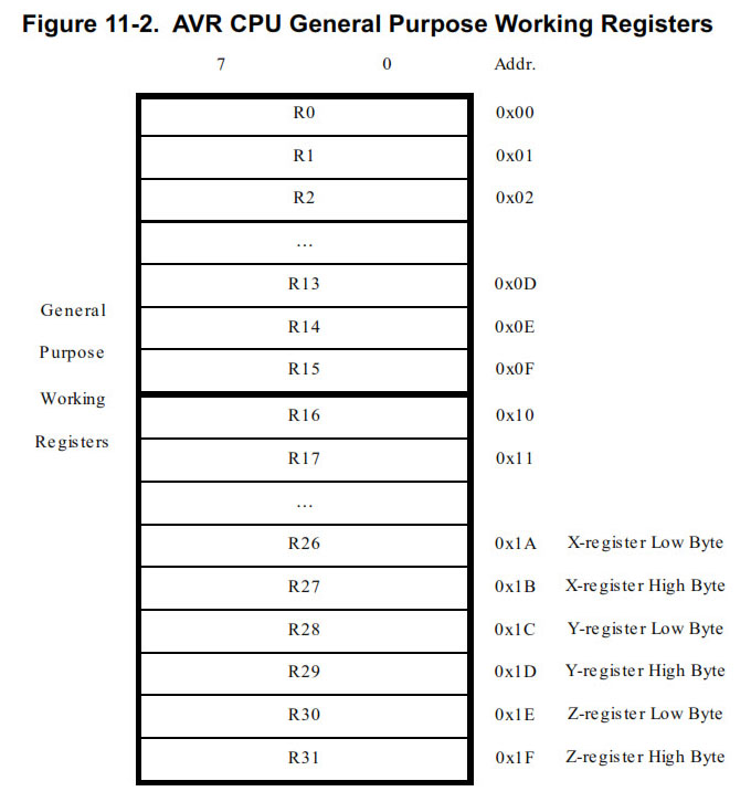
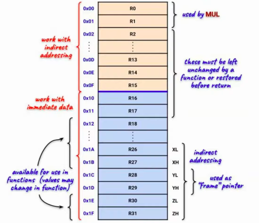
Registers
ATMega328P has 32 general purpose registers [Registers R0 to R31]
-
8 bit registers
-
Mapped to SRAM memory [Addresses between 0x00 and 0x1F]
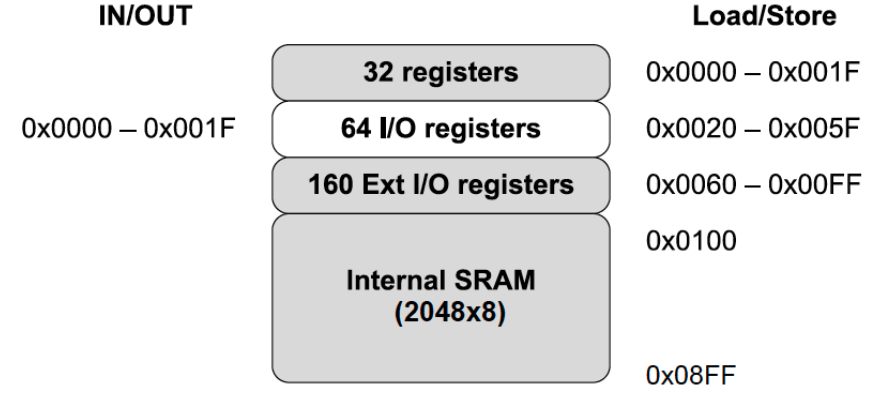
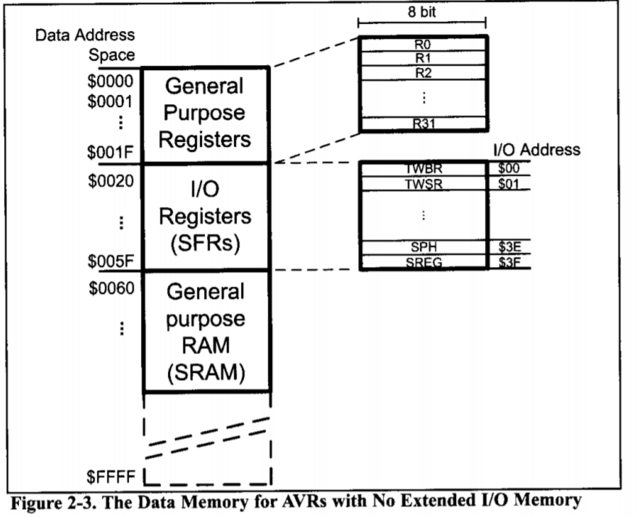
SRAM
ATMega328P has 2 Kbytes of main memory implemented with SRAM
-
Some segments are reserved
-
0x00 to 0x1F are the 32 registers
-
0x20 to 0x5F are I/O registers (Memory mapped I/O)
-
Instruction format
-
Most instructions occupy 16 bits
-
There are several formats of instruction
-
Variable length opcodes
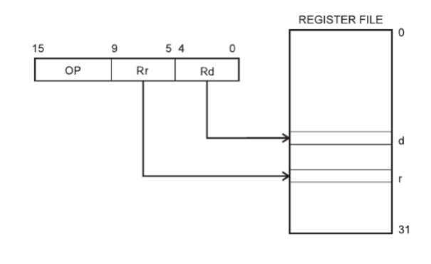
Ex. Register Direct
-
Op: Opcode
-
Rr: Source register 1
-
Rd: Source 2 and destination register
Assembly instructions
-
Assembly instructions follow the same order used in MIPS
-
OPCODE destination, source
-
ldi r16,0xF (Load immediate 0xF into register r16)
-
-
The number of operands varies according to the operation
Code (advanced level)
.global main                    ;defining a global function
        .type main, @function   ;defining the type

main:
        ldi r16,0b00100000      ;ldi loads an immediate into registers 16 through 31.
        ldi r17,0b00000000
        ; The “register” DDRB (Section 14.4 of the manual), which is at address 0x4,
        ; configures the pins of port B are for input (0) or output (1).

        ; out loads to the I/O address the value that is stored in the register

        ; Loading 0b00000001 to address 0x4, making pin 5 of Port B used as output,
        ; and the others as input
        out 0x04,r16

LOOP:
        ; Register PORTB (address 0x5) defines whether a high or low signal is sent
        ; to the output pins of port B. Let's send logic 1 (5 volts) into PB5.
        out 0x05,r17
        jmp LOOP                ; Jump to loop label (infinite loop)
#
# Makefile
#
FILENAME   = led
PORT       = /dev/cu.usbserial-A600BOBB
DEVICE     = atmega328p
PROGRAMMER = arduino
# BAUD can be 115200, 74888, 57600
BAUD       = 57600
COMPILE    = avr-gcc -Wall -Os -mmcu=$(DEVICE)

default: compile upload clean

compile:
        $(COMPILE) -o $(FILENAME) $(FILENAME).s

upload:
        avrdude -v -p $(DEVICE) -c $(PROGRAMMER) -P $(PORT) -b $(BAUD) -U flash:w:$(FILENAME)

clean:
        rm $(FILENAME)
Lecture 2
ATmega328p MCU registers
-
Registers divided into two groups based on how they are used and their functionalities
-
R16 to R31 are more versatile and useful than R0 to R15
-
Example:
-
The registers that work with immediate data (R16 to R31) store a byte of information or words (pairs of registers x, y and z).
-
//-------------------------
// C Code
//-------------------------
extern "C"{
  void start();
}

void setup(){
  start();
}

void loop(){
}
;---------------
; Assembly Code
;---------------
#define __SFR_OFFSET 0x00
#include "avr/io.h"
;------------------------
.global start
;------------------------
start:
    LDI   R16, 0xFF           ;load immediate byte 0xFF into register
;    LDI   R15, 0xFF           ;trying to use a different register
    RET                       ;return to setup() function
;---------------------------------------------------------------------------
-
On the other hand, registers R0 to R15 work with indirect addressing, which means that we can store a byte located in a memory location. This code will also work with R16 and R17, but its contents cannot be changed by functions.
//-------------------------
// C Code
//-------------------------
extern "C"{
  void start();
}

void setup(){
  start();
}

void loop(){
}
;---------------
; Assembly Code
;---------------
#define __SFR_OFFSET 0x00
#include "avr/io.h"
;------------------------
.global start
;------------------------
start:
    LDS   R12, 0x200          ;load direct from data space byte at memory
                              ;location 0x200 into register
    RET                       ;return to setup() function
;---------------------------------------------------------------------------
-
The 3 word registers x, y and z can handle indirect addressing and immediate storage. The y-register can be for storing the frame point
-
R0 and R1 store the 16-bit result of a multiplication performed by opcode MUL. Mul will multiply 2 bytes and its 16-bit result is stored in R1 (MSB) and R0 (LSB)
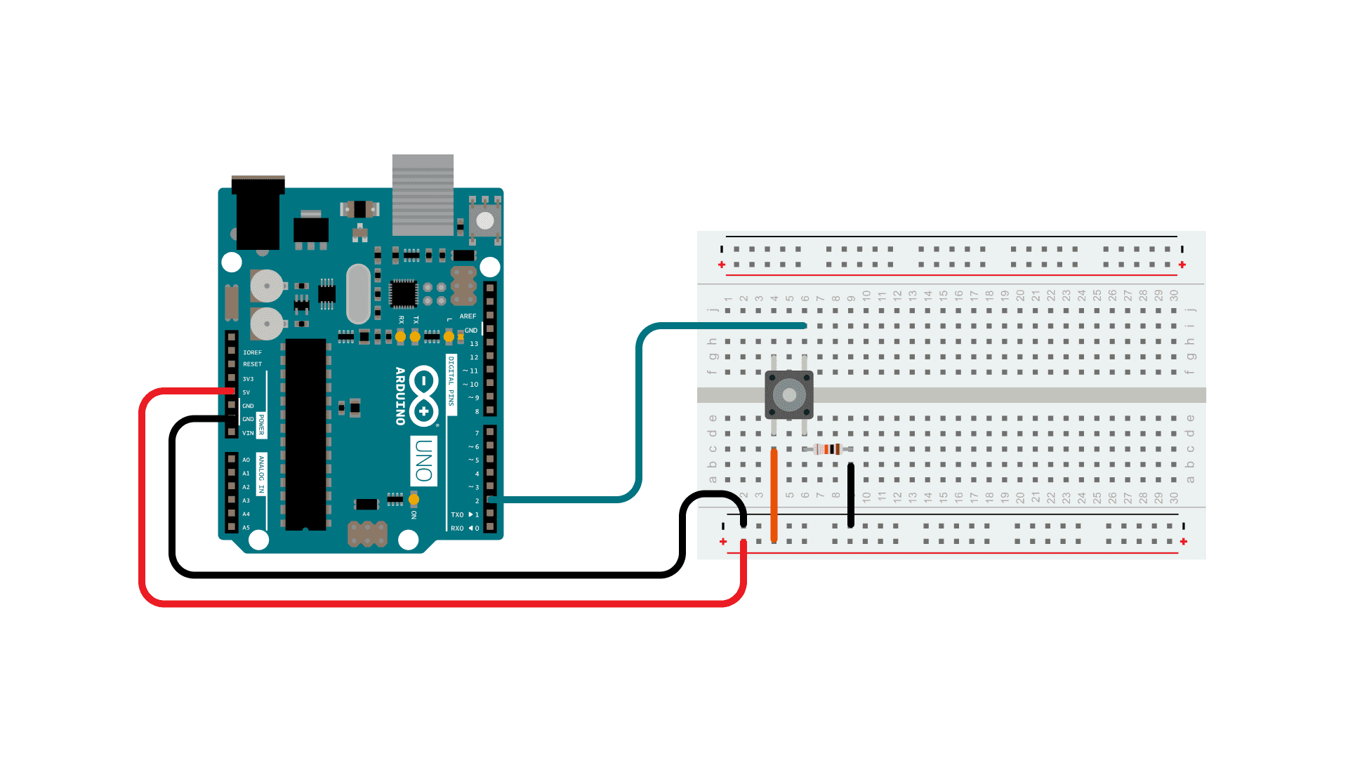
Button controlling an Led
The purpose of this section is to provide the fundamentals to control an LED using a button. This objective will be achieved through the analysis of the programs button.ino and button.S built using functions from the AVR Instruction Set Manual.
Item |
Quantidade |
Plataforma Arduino |
1 |
Cabo USB |
1 |
Protoboard |
1 |
Led |
1 |
Resistor de 200 ohms |
1 |
Resistor de 10K ohms |
1 |
Botão |
1 |
//------------------------------------
// C Code to control led using button
//------------------------------------
extern "C"{
  void start();
  void btnLED(byte);
}

void setup(){
  start();
}

void loop(){
  btnLED(2); delay(200);
}
;---------------
; Assembly Code
;---------------
#define __SFR_OFFSET 0x00
#include "avr/io.h"
;------------------------
.global start
.global btnLED
;------------------------
start:
    SBI   DDRB, 5             ;set PB5 (13) as output
    CBI   DDRD, 2             ;set PD2 (2) as input
    RET                       ;return to setup() function
;---------------------------------------------------------------------------
btnLED:
ledON:
    ;SBIC = Skip if Bit in Register is Cleared
    ;SBIS = Skip if Bit in Register is Set
    SBIC  PIND, 2             ;skip next statement if button not pressed
    RJMP  ledOFF              ;jump to ledOFF
    SBI   PORTB, 5            ;set D19 to high
    RJMP  ledON               ;return to label ledON
ledOFF:
    CBI   PORTB, 5            ;turn OFF LED if button is not pressed
    RET
Lecture 3
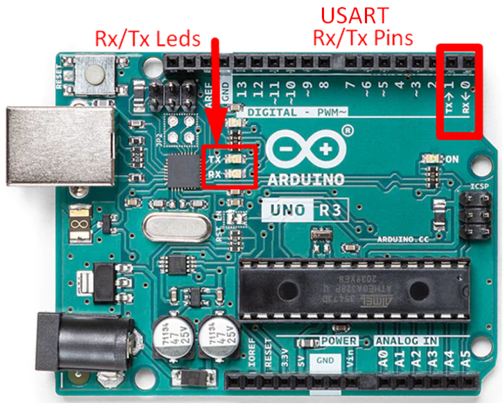
Serial Communication
Program serial port to transmit/receive data using synchronous or assynchronous modes (USART).
USART Registers

-
UBRR
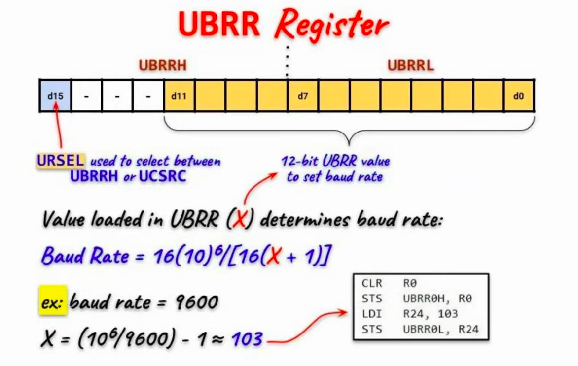
-
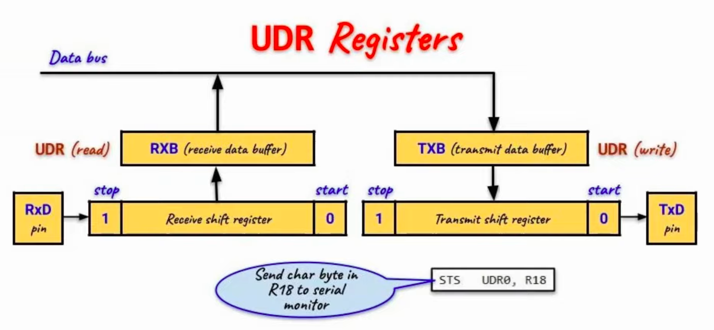
UDR
-
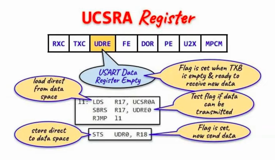
UCSRA
-
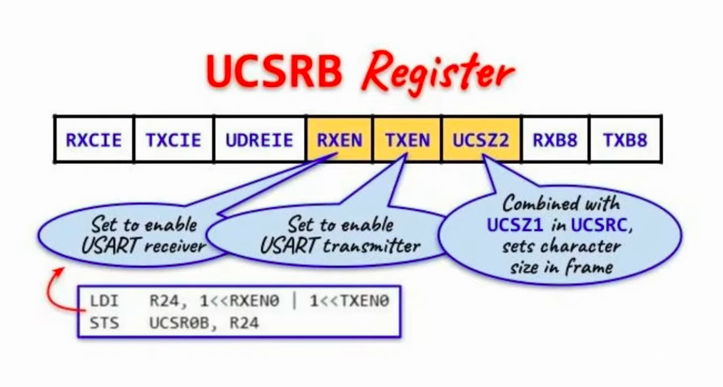
UCSRB
-
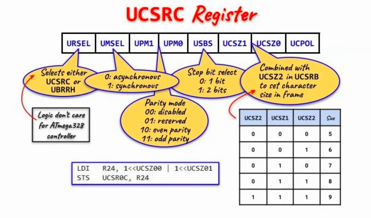
UCSRC
Review about registers
Write on Serial Port
The purpose of this section is to provide the fundamentals to send mensage from Atmega328p to PC. This objective will be achieved through the analysis of the programs serial.ino and serial.S built using functions from the AVR Instruction Set Manual.
Item |
Quantidade |
Plataforma Arduino |
1 |
Cabo USB |
1 |
//------------------------------------------------
// Programming Serial Port - Printing Text Message
//------------------------------------------------
extern "C"
{
  void init_serial();
  void print_msg();
}
//----------------------------------------------------
void setup()
{
  init_serial();
}
//----------------------------------------------------
void loop()
{
  print_msg();
}
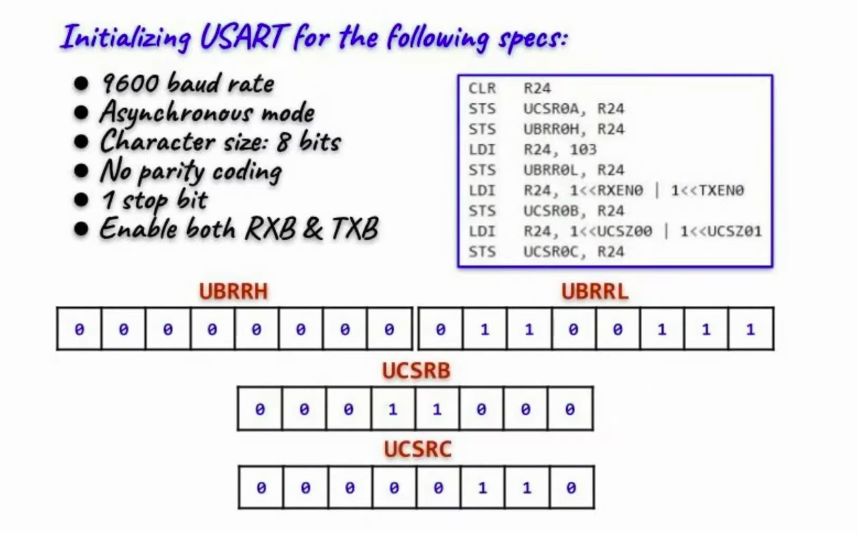
;------------------------
; Assembly Code
;------------------------
#define __SFR_OFFSET 0x00
#include "avr/io.h"
;------------------------
.global init_serial
.global print_msg
;------------------------
init_serial:
    CLR   R24
    STS   UCSR0A, R24               ;clear UCSR0A register
    STS   UBRR0H, R24               ;clear UBRR0H register
    LDI   R24, 103                  ;& store in UBRR0L 103 value
    STS   UBRR0L, R24               ;to set baud rate 9600
    LDI   R24, 1<<RXEN0 | 1<<TXEN0  ;enable RXB & TXB
    STS   UCSR0B, R24
    LDI   R24, 1<<UCSZ00 | 1<<UCSZ01;asynch, no parity, 1 stop, 8 bits
    STS   UCSR0C, R24
    RET
;-------------------------------------------------------------------------
print_msg:
    LDI   R30, lo8(message)
    LDI   R31, hi8(message)         ;Z points to string message
agn:LPM   R18, Z+                   ;load char of string onto R18
    CPI   R18, 0                    ;check if R18=0 (end of string)
    BREQ  ext                       ;if yes, exit
    ;--------------------------------------------------------------------
l1: LDS   R17, UCSR0A
    SBRS  R17, UDRE0                ;test data buffer if data can be sent
    RJMP  l1
    STS   UDR0, R18                 ;send char in R18 to serial monitor
    ;--------------------------------------------------------------------
    RJMP  agn                       ;loop back & get next character
    ;--------------------------------------------------------------------
ext:RCALL delay_sec
    RET
;------------------------------------------------------------------------
message:
    .ascii "Programming Serial Interface!" ;even number of characters!!!
    .byte 10,13,0   ;newline character, enter and null character
;------------------------------------------------------------------------
delay_sec:                          ;3s delay
    LDI   R20, 255
l4: LDI   R21, 255
l5: LDI   R22, 255
l6: DEC   R22
    BRNE  l6
    DEC   R21
    BRNE  l5
    DEC   R20
    BRNE  l4
    RET